

- Company
- Products
- New Arrival
- Hot Buy
- Downloads
- V3 Submersible Pumps
- V4 Submersible Pumps
- V6 Submersible Pumps
- V8 Submersible Pumps
- Dewatering Pumps
- Effluent Pumps
- Sewage Pumps
- Submersible Pumps
- Openwell Submersible Pumps
- Vertical Openwell Pumps
- Centrifugal Monoblock Pumps
- Domestic Monoblock Pumps
- Stainless Steel Submersible Pumps
- Sea Water Pumps
- Customized Product
- Pumps Spares
- Control Panel
- Cables
- Process
- Technical
- Support
- Media
- Inquiry
- Contacts
Centrifugal Pumps2
Centrifugal: "Moving or directed away from the center (or axis)"
Centrifugal pumps are the most common type of pump used in plumbing systems. This article explores the basic design concepts and functional principals of these pumps.
Quick Link
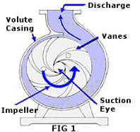
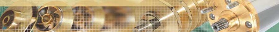
Fig 1 illustrates a cross-section of a typical centrifugal pump.
Fluid enters the inlet port at the center of the rotating impeller, or the suction eye.
As the impeller spins in a counter-clockwise direction, it thrusts the fluid outward radially, causing centrifugal acceleration.
As it does this, it creates a vacuum in its wake, drawing even more fluid into the inlet.
Centrifugal acceleration creates energy proportional to the speed of the impeller. The faster the impeller rotates, the faster the fluid movement and the stronger its force. This energy is harnessed by introducing resistance.
![]() Remember, a pump does not create pressure; it only provides flow.
Remember, a pump does not create pressure; it only provides flow.
Pressure is a measure of the amount of resistance to that flow.
A centrifugal pump has two main components, one moving and one stationary.
The moving component consists of an impeller and a shaft.
The stationary component consists of a casing, cover, and bearings.
These are illustrated at the left, in Fig 2.
Moving Components: Impellers & Shafts
Impeller
Impellers are the rotating blades that actually move the fluid. They are connected to the drive shaft that rotates within the pump casing. The impeller is designed to impart a whirling or motion to the liquid in the pump.
Impellers are classified in a number of different ways:
Direction of flow relative to the axis of the shaft.
Direction of flow relative to the axis of the shaft.
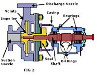
Mechanical construction (FIG 3)
- Radial flow
- Axial flow
- Mixed flow
- Single-suction (Liquid inlet on one side)
- Double-suction (Liquid inlet on both sides)
- Open: No shrouds or wall to enclose the vanes
- Closed: Shrouds or sidewall enclosing the vanes
- Semi-open or vortex type.
Open and semi-open impellers are less prone to clogging, but require manual adjustment to the volute or back-plate to prevent internal re-circulation.
Closed impellers require wear rings, which must be replaced periodically, presenting a maintenance problem.
Vortex impellers are effective for solids and fibrous materials but they are less efficient than other designs.
Stages
The number of impellers determines the number of stages of the pump.
SingleStage pump has just one impeller and is better for low head service
Two-Stage pumphas two impellers mounted in series for medium head service.
Multi-Stage pump has three or more impellers mounted in series for high head service such as in deep well pumps.
Impeller Class (Shape)
Specific Speed is used to classify pump impellers as to their type and proportions.
It is defined as the speed in RPMs (revolutions per minute) at which a similar impeller would have to operate in order to deliver one gallon per minute flow against one-foot head.
The specific speed determines the general shape or class of the impellers.
Radial flow impellers develop head principally through centrifugal force. Radial impellers are generally used in low flow high head designs, while Axial impellers are used in high flow low head designs. Pumps of higher specific speeds develop head partly by centrifugal force and partly by axial force.
Shafts
Shaft Sleeves extend beyond the outer face of the seal gland plate and protect the shafts from erosion, corrosion, and wear.
Leakage between the shaft and the sleeve is different
from leakage through the mechanical seal
Shaft Couplings compensate for axial growth of the shaft and transmit torque to the impeller. They may be either rigid or flexible.
Rigid couplings are used when there is chance of misalignment. Flexible couplings are more forgiving, and may be either elastomeric (using rubber or polymer parts) or non-elastomeric (using metallic parts).
Stationary Components: Casing
Casing
The pump casing creates the first resistance. The liquid decelerates still more in the discharge nozzle, where its velocity is converted to pressure
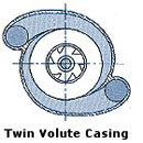
Casings are generally either volute or circular.
A volute is a curved funnel that increases in size to the discharge port. As its size increases, the volute reduces the speed of the liquid and increases the output pressure.
This helps to balance hydraulic pressure on the shaft; however, running volute-style pumps at slow speeds puts undue stress on the shaft, which in turn increases wear-and-tear on the seals and bearings, as well as on the shaft itself.
Volute casings build a higher head, but circular casings are generally used on higher capacity pumps. Circular casings have stationary diffusion vanes around the impeller that convert velocity energy to pressure energy. Diffusers are typically used in multi-stage pumps.
Casings are either solid or split.
In a solid casings design the entire casing is in one piece. Split casings are made of two or more parts fastened together, split either horizontally (axially split), or vertically (radially split). Wear rings seal the casing from the impeller.
Suction and discharge nozzles are built into the casings. They are typically made in one of the following ways:
End suction/Top discharge. The discharge nozzle is perpendicular to the shaft.
Top suction /Top discharge. Both nozzles are perpendicular to the shaft. This pump is always a radially split case pump.
Side suction / Side discharge. Both nozzles are perpendicular to the shaft. This pump can have either an axially or radially split case type.
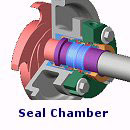
The space between the shaft and casing is called the chamber.
If a mechanical seal is used in the pump, the chamber is commonly referred to as a Seal Chamber.
If packing is used to form the seal, the chamber is referred to as a Stuffing Box.
Both the seal chamber and the stuffing box protect the pump against leakage where the shaft passes through the casing. They also maintain proper temperature control.
An adjustable gland helps the packing or the seal fit properly on the shaft sleeve. The throat or throttle bushing forms a close clearance around the sleeve. An internal circulating device (pumping ring) circulates fluid through a cooler or reservoir.
Bearings
The bearing housing encloses the bearings that keep the shaft in correct alignment with the stationary parts. It also includes an oil reservoir for lubrication, oiler, and cooling jacket.
Auxiliary Components
Auxiliary components generally include seal drains, vents, and cooling systems, bearing lubrication, seal chamber or stuffing box cooling, and pump pedestal cooling systems.
Auxiliary piping systems may include tubing, piping, various types of valves and gauges, thermocouples, sight flow indicators, fluid reservoirs, and all related vents and drains.
Pump Capacity
Capacity is the flow rate in gallons per minute (GPM) at which liquid is moved or pushed by the pump.
Capacity depends on the pressure, temperature, and viscosity of the liquid being pumped, the size of the pump and the shape of the cavities between the vanes, and on the size and speed of the impeller.
Note: Pressure output of pumps is measured as "feet of head" rather than "pounds per square inch"
Since liquids are essentially incompressible, capacity is directly related with the velocity of flow in the suction pipe. This relationship is as follows:
Q = 449 x V x A
Q = Capacity in gallons per minute
V = Velocity in flow in feet per second
A = Area of pipe in square ft.
Power and Efficiency
Brake Horsepower (BHP) is the actual horsepower delivered to the pump shaft, defined as follows:
BHP = Q x Hr x Sp. Gr.
3960 x Eff.
Q = Capacity in gallons per minute
Hr = Total Differential Head in absolute feet
Sp.Gr. = Specific Gravity of the liquid.
Eff. = Pump efficiency as a percentage
Water Horsepower (WHP) is the hydraulic horsepower delivered by the pump, defined as follows:
WHP = Q x Hr x Sp/Gr.
3960
Q = Capacity in gallons per minute
Hr = Total Differential Head in absolute feet
Sp.Gr. = Specific Gravity of the liquid.
The constant (3960) is the number of foot-pounds in one horsepower (33,000) divided by the weight of one gallon of water (8.33 pounds).
Brake horsepower is always greater than hydraulic horsepower due to the friction in the pump. Pump efficiency is the ratio of these two values.
Pump Efficiency = WHP
BHP
Best Efficiency Point (BEP) is the capacity at maximum impeller size at which the efficiency is highest.
All points above or below BEP have a lower efficiency, and the impeller is subject vibration, heat, and cavitation. This causes premature bearing and mechanical seal failures due to shaft deflection, and heat will cause seizure of close tolerance parts and cavitation.
A high efficiency pump uses less energy ($$$) to operate than a low efficiency pump. If possible, it is best to avoid any pump that has an efficiency of 55% or less. (55% efficiency is the industry standard used to estimate the performance of a pump when the actual efficiency is unknown.)
Pump Curve
A pump curve is a simple graph which shows the performance characteristics of a particular pump.
Pump curves are created by the pump manufacturer based on test results of the various pump models the manufacturer produces.
Remember, there is always an inverse relationship between pressure and flow. Higher pressures mean lower flows. Lower pressures result in higher flows.
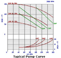 Each pump curve typically reflects a single model of pump made by the manufacturer. (A typical pump curve is shown at the right)
The top right of the chart shows the pump speed; in the chart above this is 3500 RPM. Two variables affect the pump performance, horsepower of the motor and the size of the impeller.
The left side of the curve is labeled HEAD - FT. This is the distance the pump is capable of lifting the fluid. The bottom of the curve is labeled US GPM. This is the flow that the pump produces.
The red upper curved lines represent the various impeller sizes. The green straight lines represent the motor horsepower ratings available for this pump. Together they represent the best performance the pump is capable of with a selected motor or impeller size.
If a pump is only available with one motor, it will not have separate horsepower lines. If the pump is available with only one size of impeller, there will be just a single line on the entire pump curve!
Based on the above curve, an output of 125 ft hd at 100 GPM would require a 5 HP motor and a 6 inch diameter impeller. Similarly, an output of 70 ft. hd. at 80 GPM would require a 3 HP motor with a 5 inch diameter impeller.
NPSH FT (shown in the lower right of the graph) is the maximum height that a pump can be above the water. This does not apply to submersible, jet, or turbine pump because the pump is underwater. It also does not apply to booster pumps because water is already being forced into them from the water source.
Pumps can sometimes be ordered with custom impeller sizes. This often does not cost much more than a stock pump, but it will delay the delivery since they are custom built.